A Surface Mounted component is an item that will be assembled to a manifold face through Bolt Holes. Examples are: NG6- NG10… valves, Slip-In covers, Flanges, all surface mounted valves. Matings for a Surface Mounted valve differ from those of a cartridge since MDTools must properly rotate the component to match the Footprint direction.
4 matings are required by MDTools Set Assembly constraint command:
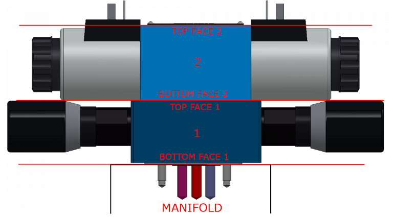
bottom face = plane where the component will touch the manifold face
Top face = plane where another component will be assembled on top (i.e. stackable valves)
Axis 1 and 2 = axis to define orientation MDTools rules for axis definition are: a) if only Bolt Holes are present in the cavity: Axis 1 = BH1, Axis 2 = BH2 b) if only one Locating Pin is present: Axis 1 = LP, Axis 2 = BH1 c) if 2 locating Pins are present: Axis 1 = LP1, Axis 2 = BH2
Following images shows a, b and c cases:
Axis rule definition with BH1 and BH2
Click Here
Axis rule definition with LP and BH1
Click Here
Axis rule definition with LP1 and LP2
Click Here
Bottom face and top face rules must follow what is described by this image:
Video showing how to set assembly constraints in MDTools 900 series for SolidWorks.
Utilizziamo i cookie per essere sicuri che tu possa avere la migliore esperienza sul nostro sito. Se continui ad utilizzare questo sito noi assumiamo che tu ne sia felice.