A Surface Mounted component is an item that will be assembled to a manifold face through Bolt Holes. Examples are: NG6- NG10… valves, Slip-In covers, Flanges, all surface mounted valves. Matings for a Surface Mounted valve differ from those of a cartridge since MDTools must properly rotate the component to match the Footprint direction.
4 matings are required by MDTools Set Assembly constraint command:
bottom face = plane where the component will touch the manifold face
Top face = plane where another component will be assembled on top (i.e. stackable valves)
Axis 1 and 2 = axis to define orientation MDTools rules for axis definition are: a) if only Bolt Holes are present in the cavity: Axis 1 = BH1, Axis 2 = BH2 b) if only one Locating Pin is present: Axis 1 = LP, Axis 2 = BH1 c) if 2 locating Pins are present: Axis 1 = LP1, Axis 2 = BH2
Following images shows a, b and c cases:
Axis rule definition with BH1 and BH2
Click Here
Axis rule definition with LP and BH1
Click Here
Axis rule definition with LP1 and LP2
Click Here
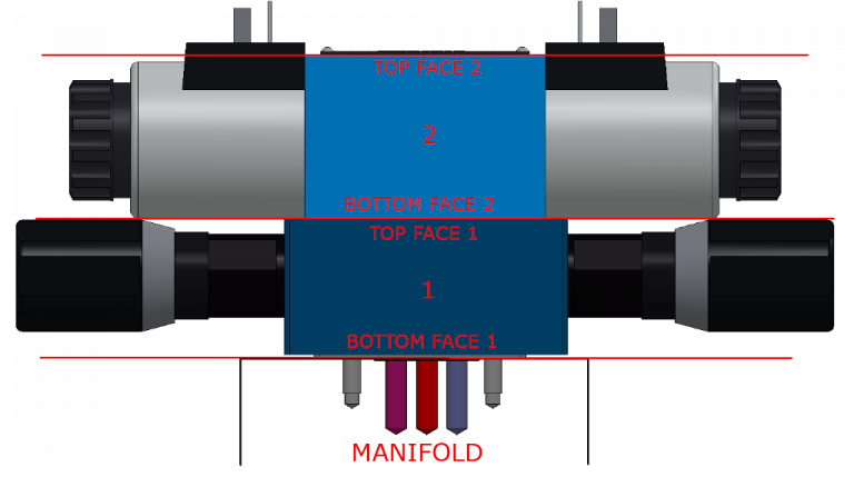
Bottom face and top face rules must follow what is described by this image:
Video showing how to set assembly constraints in MDTools 900 series for SolidWorks.
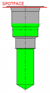
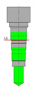
Cartridge valves fit into cavities, for MDTools we have 2 type of cavities: standard and “sun cavities”. Standard means a cavity with C’Bore, Sun Cavities take origin to Sun Hydraulics valves, they mate with a Locating Shoulder that’s inside the cavity. Below we see 2 examples of cavities taken from MDTools Library Manager.
Standard Cavity, mating plane = SpotFace
Sun Cavity, mating plane = Locating Shoulder (LS)
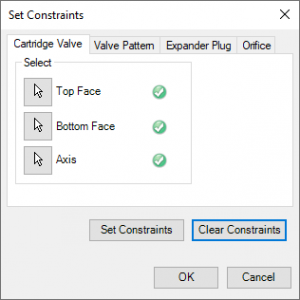
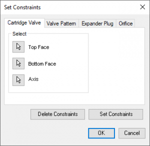
Cartridge valve rules are set through MDTools Set Constraints dialog. For a cartridge valve we need 3 constraints: top face, bottom face, axis.
Each of these geometries must be set directly in the valve 3d model
MDTools Set Constraints command is available in both assembly and part environment for SolidWorks and Autodesk Inventor.
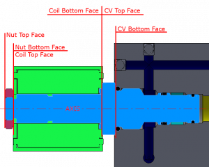
Top face is always required, it is not relevant when the cartridge will not have any additional item assembled on top (i.e. a coil, a nut).
Coils, nut… will require same constraints to be assembled automatically by MDTools
Below example of Bottom Face / Top Face for Cartridge, Coil and Nut for a Solenoid Valve assembly.
Video showing how to set Constraints and create assembly with MDTools on SolidWorks. MDTools on Autodesk Inventor behaves very similarly so each item described is applicable. If you need more info feel free to contact us
Fro MDTools we have 2 type of plugs: threaded with Spot/Face and expander.
Plugs without spotface must be threated like Expander with respect to Assembly Rules.
Example of threaded plug cavity
Example of Expander cavity
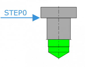
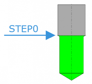
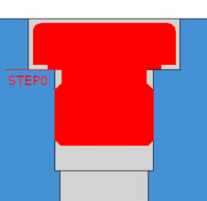
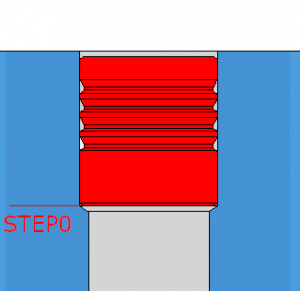
In both cases, user must identify cavity STEP0. Below images show how plugs must be assembled on the 3d model.
Threaded plugs follow “Cartridge Valve” assembly rules.
In this section user is supposed to select
Top Face = non relevant here but you must select (select external plug face)
Bottom Face = mating plane, surface that will match cavity STEP0 plane
Axis = plug axis (thread cylinder axis)
It’s possible to select any planar face from 3d model instead of planes. In case face is not planar, you can create plane with cad commands and select them instead.
If plug is assembled bottom-up, flip bottom face plane normal by using dedicated commands in Inventor or SolidWorks.
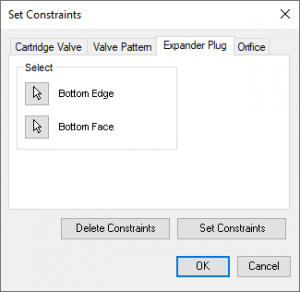
Expander follow Expander Plug assembly rules. For MDTools 700 Series (Inventor) only bottom edge is required. MDTools 900 series for SolidWorks requires 2 constraints, Bottom Edge and Bottom Face, because of different 3D CAD engine mating management.
Utilizziamo i cookie per essere sicuri che tu possa avere la migliore esperienza sul nostro sito. Se continui ad utilizzare questo sito noi assumiamo che tu ne sia felice.